Overview
When printing large assemblies or parts that need to fit together precisely, dimensional accuracy is extremely important. The overall dimensional accuracy of each printed part will affect the entire printed assembly.
A number of factors affect dimensional accuracy. Proper calibration, belt tension, flow rate, linear components, temperatures, materials, and design compensation all play a role in dimensional accuracy.
Effects of Poly Count on Circle Precision
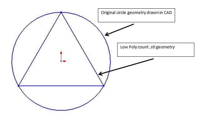
One of the challenges with 3D printing is obtaining the correct size for hole features. Currently, the preferred file format for 3D printing is the .stl (Standard Tessellation Language) format. The STL file format describes 3D images as a series of triangles of various sizes, as seen in the figure below:
The number and size of the triangles is dictated by the “Preferences” settings of your CAD (Computer Aided Drawing) program. In the extreme example where the CAD model is saved as a “Low Poly count,” the circle or hole feature would be represented by six triangles and the top view would look like the figure below. When 3D printing this circular feature, the tool path would follow the triangle geometry and produce a hole much smaller than the original CAD geometry.
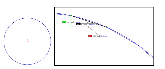
The desire to more accurately represent a true circle would lead to increasing the poly count to add more triangles to the model, and might look like the image below:
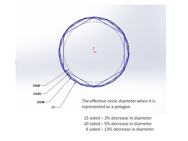
The above image shows a poly count 10x greater than the original “low poly count” example. Increasing the number of triangles gives the 3D printer a better, more accurate circular tool path, but at a cost of requiring a higher throughput of data for motion control. If the positional data being fed into the printer has too much resolution, one of the following may be a factor:
- The machine may not be capable of accurately recreating the resolution
- The printer controller may not be able to process the positional data fast enough to maintain an optimal print speed.
The happy medium is achieved when the poly count is great enough to accurately describe the circle for the needs of the printed part, but also low enough to allow the motion control system to print the circle at an optimal speed.
Effects of Perimeter Order on Circle Size
The inside diameter of holes are affected by the order of operations in 3D printing. In the image below, the slicer settings have Perimeters = 2. Notice the outside of the box and the inside of the holes have two perimeters. This is often done to strengthen the part and increase the print quality. Most slicing software allows you to decide if the print starts with the inside perimeter and moves to the outside perimeter.
When starting with the inside perimeter, the part has improved surface finish. When starting with the outside perimeter, the part has improved dimensional accuracy for holes.
The image below shows the actual tool path for a series of circles with diameters ranging from 1/8” to 1”. Notice that each circle is made from many small line segments.
Actual printed part below:
Note: Different slicing programs may also influence the dimensional accuracy of part features.
Questions or concerns? Reach out to our support team at support@re:3D.org or open a support ticket.
Comments
0 comments
Please sign in to leave a comment.